Fiber Optic Cabling
Optical Fiber
This section goes into great detail on fiber and how it works – for those who are interested! As a quick summary, fiber optic cable comes in two basic types – single-mode and multi-mode. It transports light signal in two different ways – digital and analog. Digital is basically pulses of light and is used in data applications. Mulit-mode 62.5 micron fiber was the most common type and size of fiber used in most short distance data applications until a few years ago. However, as bandwidth needs increased in recent years, multi-mode 50 micron fiber became more common. But, again bandwidth demands increased so more and more customers are using single mode for short distances to gain maximum bandwidth and “future-proofing” their fiber backbone installations. Analog is used in cellular transport applications and will not be covered in this section. Check this link for our cellular in building services.
Fiber Optics is the communications medium that works by sending optical signals down hair-thin strands of extremely pure glass or plastic fiber. The light is “guided” down the center of the fiber called the “core”. The core is surrounded by a optical material called the “cladding” that traps the light in the core using an optical technique called “total internal reflection.” The fiber itself is coated by a “buffer” as it is made to protect the fiber from moisture and physical damage. The buffer is what one strips off the fiber for termination or splicing.
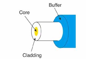
The core and cladding are usually made of ultra-pure glass, although some fibers are all plastic or a glass core and plastic cladding. The core is designed to have a higher index of refraction, an optical parameter that is a measure of the speed of light in the material, than the cladding, which causes “total internal reflection” to trap light in the core up to a certain angle, which defines the “numerical aperture” of the fiber. More technical details are below.
Glass fiber is coated with a protective plastic covering called the “primary buffer coating” that protects it from moisture and other damage. More protection is provided by the “cable” which has the fibers and strength members inside an outer protective covering called a “jacket”.
Fiber Types: Multimode & Singlemode, Core/Cladding Size
The two types of fiber are multimode and singlemode. Within these categories, fibers are identified by their core composition (MM step-index or graded-index) and core/cladding diameters expressed in microns (one millionth of a meter), e.g. 50/125 micron graded-index multimode fiber. Most glass fibers are 125 microns in outside diameter – a micron is one one-millionth of a meter and 125 microns is 0.005 inches- a bit larger than the typical human hair.
Multimode fiber has light traveling in the core in many rays, called modes. It has a larger core (almost always 50 or 62.5 microns) which supports the transmission of multiple modes (rays) of light. Multimode is generally used with LED sources at wavelengths of 850 and 1300 nm (see below!) for slower local area networks (LANs) and lasers at 850 (VCSELs) and 1310 nm (Fabry-Perot lasers) for networks running at gigabits per second or more.
Singlemode fiber has a much smaller core, only about 9 microns, so that the light travels in only one ray (mode.) It is used for telephony and CATV with laser sources at 1310 and 1550 nm because it has lower loss and virtually infinite bandwidth.
1300 or 1310nm? Fiber is filled with jargon that is traditional and often obtuse in meaning. The 1300/1310 issue goes back to the beginning. AT&T’s long-wavelength lasers were statistically centered around 1310nm (but varied from 1290-1330 or more) so they adopted the 1310nm nomenclature. LEDs with a wider and more varied spectral output (~1260-1350nm with spectral widths of 60-150nm depending on the construction) became known as 1300nm devices. When NBS (now NIST) created a calibration standard for power meters, they used 850, 1300 and 1550nm so meter calibration is usually at those wavelengths, although some manufacturers offer both 1300 and 1310 or call it 1300/1310 because it is an irrelevant difference in calibration. Plastic Optical Fiber (POF) is large core ( about 1mm) fiber, usually step index, that is used for short, low speed networks.
PCS/HCS (plastic or hard clad silica, plastic cladding on a glass core) has a smaller glass core (around 200 microns) and a thin plastic cladding.
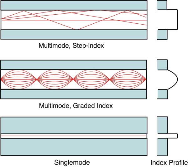
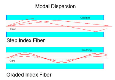
Fiber types. The left of the drawing shows the core/cladding diameters. The right part of the drawing shows the index profile of the fiber. The index profile shows the relative index of refraction of the material used in making the fiber. Total Internal Reflection The index of refraction of glass or any optical material is a measure of the speed of light in the material and changes in index of refraction are what causes light to bend – as shown in this photo of a plastic rod in a pond:  Beyond a certain angle, the refraction will cause light to be reflected from the surface. Optical fiber uses this reflection to “trap” fiber in the core of the fiber by choosing core and cladding materials with the proper index of refraction that will cause all the light to be reflected if the angle of the light is below a certain angle. We call that “total internal reflection.” There is an angle that for any given fiber defines total internal reflection. At higher angles a ray of light will be refracted but not enough so it is lost in the cladding of the fiber. Below that angle, it will be reflected back into the core of the fiber and transmitted to the end of the fiber. The angle of total internal reflection defines the “numerical aperture” (NA) of the fiber, a standard fiber specification. Step Index Multimode Fiber Step index multimode fiber was the first fiber design. It has a core of one type of It has higher attenuation and is too slow for many uses, due to the dispersion caused by the different path lengths of the various modes travelling in the core. Step index fiber is not widely used – generally only POF and PCS/HCS (plastic or hard clad silica, plastic cladding on a glass core) use a step index design today.
Graded Index Multimode Fiber
Graded index multimode fiber uses variations in the composition of the glass in the core to compensate for the different path lengths of the modes. It offers hundreds of times more bandwidth than step index fiber – up to about 2 gigahertz. Two types are in use, 50/125 and 62.5/125, where the numbers represent the core/cladding diameter in microns. Graded index (GI) fiber has a range of materials in the core which are chosen to minimize modal dispersion caused by different path lengths of different modes being transmitted down the fiber. The core index profile is curved – a parabola to be exact – with lower index glass on the outside of the core. The lower index glass transmits the higher angle light rays (called high order modes) faster than the lower index glass near the center of the core.
The index profile of the core of multimode GI fiber is not continuous, which is hard if not impossible to manufacture, but is in steps, from hundreds of steps to thousands depending on the fiber design and manufacturing process. As a mode of light goes through each step, it is bent slightly until it is reflected back toward the core of the fiber. Index of refraction is related to the speed of light in the fiber; N=C/V, so a higher index of refraction indicates that light travels at a slower speed (V) relative to the speed of light in a vacuum (C.) Since the light is going into a lower index of refraction material in the outside of the core, it speeds up compared to the speed at the center of the core. By carefully designing and manufacturing the fiber, you can get the average speed of a higher-order mode approximately the same as the modes going straight down the fiber, reducing modal dispersion.
 While the majority of graded-index fiber is all glass, there are some GI POF fibers also. Singlemode Fiber Singlemode fiber shrinks the core down so small that the light can only travel in one ray or mode, hence the name singlemode.
 Since there is only one mode, there is no problem with modal dispersion and the choice of core material can reduce chromatic dispersion (see below) which increases the bandwidth to almost infinity – but it’s practically limited to about 100,000 gigahertz – that’s still a lot! Singlemode fiber has a core diameter of 8-10 microns, specified as “mode field diameter,” the effective size of the core, and a cladding diameter of 125 microns. Specialty Fibers have been developed for applications that require unique fiber performance specifications. Erbium-doped singlemode fibers are used in fiber amplifiers, devices used in extremely long distance networks to regenerate signals. Fibers are optimized for bandwidth at wavelengths appropriate for DWDM systems or to reverse chromatic dispersion. This is an active area of fiber development.
Manufacturing Optical Fiber
The manufacturing of optical fiber to sub-micron precision is an interesting process involving making ultra-pure glass and pulling it into strands the size of a human hair. The process begins with the manufacture of a perform, a large diameter glass rod which has the exact same optical cross section as a fiber but is hundreds of times larger. The end of the rod is heated and a thin strand of fiber is pulled from the perform and wound on large reels. After manufacture, the fiber is tested and then made into cable.
Here is more information on fiber manufacturing.
Fiber Sizes and Types Fiber comes in two types, singlemode and multimode. Except for fibers used in specialty applications, singlemode fiber can be considered as one size and type. If you deal with long haul telecom or submarine cables, you may have to work with specialty singlemode fibers.
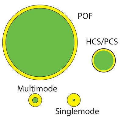 Relative sizes of all fibers
 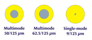 Comparison of core/cladding sizes Multimode fibers originally came in several sizes, optimized for various networks and sources, but the data industry standardized on 62.5 core fiber in the mid-80s (62.5/125 fiber has a 62.5 micron core and a 125 micron cladding. It’s now called OM1 standard fiber.) Recently, as gigabit and 10 gigabit networks have become widely used, an old fiber design has been revived. 50/125 fiber was used from the late 70s with lasers for telecom applications before singlemode fiber became available. 50/125 fiber (OM2 standard) offers higher bandwidth with the laser sources used in the gigabit LANs and can allow gigabit links to go longer distances. Newer OM3 or laser-optimized 50/125 fiber today is considered by most to be the best choice for multimode applications. To identify the types of fiber in a cable, there are standardized color codes for the cable jacket covered under TIA-598. Here is more information on color codes for cables and connectors.
*Some standards now include attenuation at 1383nm (water peak) which is generally no higher than at 1310nm. CAUTION: You cannot mix and match fibers! Trying to connect singlemode to multimode fiber can cause 20 dB loss – that’s 99% of the power. Even connections between 62.5/125 and 50/125 can cause loss of 3 dB or more – over half the power. More on mismatched fibers. Fiber Specifications The usual fiber specifications are size (core/cladding diameter in microns), attenuation coefficient (dB/km at appropriate wavelengths) and bandwidth (MHz-km) for multimode fiber and chromatic and polarization-mode dispersion for singlemode fiber. While manufacturers have other specs for designing and manufacturing the fiber to industry standards, like numerical aperture (the acceptance angle of light into the fiber), ovality (how round the fiber is), concentricity of the core and cladding, etc., these specs do not generally affect users who specify fibers for purchase or installation. Here is more information on testing fiber specifications. Some fibers have been designed to be much less sensitive to bend-induced losses. These “bend-insensitive” fibers are designed for use as patchcords or in tight premises appplications where regular fibers would suffer losses. Here is more information on bend-insensitive fibers.
Attenuation The primary specification of optical fiber is the attenuation. Attenuation means a loss of optical power. The attenuation of an optical fiber is expressed by the attenuation coefficient which is defined as the loss of the fiber per unit length, in dB/km.

The attenuation of the optical fiber is a result of two factors, absorption and scattering. The absorption is caused by the absorption of the light and conversion to heat by molecules in the glass. Primary absorbers are residual OH+ and dopants used to modify the refractive index of the glass. This absorption occurs at discrete wavelengths, determined by the elements absorbing the light. The OH+ absorption is predominant, and occurs most strongly around 1000 nm, 1400 nm and above1600 nm. The largest cause of attenuation is scattering. Scattering occurs when light collides with individual atoms in the glass and is anisotropic. Light that is scattered at angles outside the numerical aperture of the fiber will be absorbed into the cladding or transmitted back toward the source Scattering is also a function of wavelength, proportional to the inverse fourth power of the wavelength of the light. Thus if you double the wavelength of the light, you reduce the scattering losses by 2 to the 4th power or 16 times. For example, the loss of multimode fiber is much higher at 850 nm ( called short wavelength) at 3 dB/km, while at 1300 nm (called long wavelength) it is only 1 dB/km. That means at 850 nm, half the light is lost in 1 km, while only 20% is lost at 1300 nm. Therefore , for long distance transmission, it is advantageous to use the longest practical wavelength for minimal attenuation and maximum distance between repeaters. Together, absorption and scattering produce the attenuation curve for a typical glass optical fiber shown above. Fiber optic systems transmit in the “windows” created between the absorption bands at 850 nm, 1300 nm and 1550 nm, where physics also allows one to fabricate lasers and detectors easily. Plastic fiber has a more limited wavelength band, that limits practical use to 660 nm LED sources.More: Wavelength Bands Used For Fiber Optic TransmissionBandwidth Multimode fiber’s information transmission capacity is limited by two separate components of dispersion: modal and chromatic. Modal dispersion comes from the fact that the index profile of the multimode fiber isn’t perfect. The graded index profile was chosen to theoretically allow all modes to have the same group velocity or transit speed along the length of the fiber. By making the outer parts of the core a lower index of refraction than the inner parts of the core, the higher order modes speed up as they go away from the center of the core, compensating for their longer path lengths.
In an idealized fiber, all modes have the same group velocity and no modal dispersion occurs. But in real fibers, the index profile is a piecewise approximation and all modes are not perfectly transmitted, allowing some modal dispersion. Since the higher order modes have greater deviations, the modal dispersion of a fiber (and therefore its laser bandwidth) tends to be very sensitive to modal conditions in the fiber. Thus the bandwidth of longer fibers degrades nonlinearly as the higher order modes are attenuated more strongly.
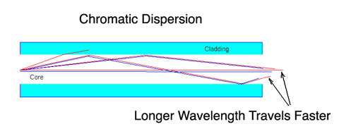
The second factor in fiber bandwidth, chromatic dispersion, affects both multimode and singlemode fiber. Remember a prism spreads out the spectrum of incident light since the light travels at different speeds according to its color and is therefore refracted at different angles. The usual way of stating this is the index of refraction of the glass is wavelength dependent. Thus a carefully manufactured graded index profile can only be optimized for a single wavelength, usually near 1300 nm, and light of other colors will suffer from chromatic dispersion. Even light in the same mode will be dispersed if it is of different wavelengths. Chromatic dispersion is a big problem with LED sources in MM fiber, which have broad spectral outputs, unlike lasers which concentrate most of their light in a narrow spectral range. Systems like FDDI, based on broad spectral output surface emitter LEDs, suffered such intense chromatic dispersion that transmission was limited to only two km of 62.5/125 fiber. Chromatic dispersion (CD) also affects long links in singlemode systems, even with lasers, so fiber and sources are optimized to minimize chromatic dispersion in the long distance links. More on CD and PMD.